GPU WORLD · ENGINEERING GUIDE
How to size a CDU for a GPU rack
Size the coolant distribution unit (CDU) for the heat that reaches the liquid loop. Then check that it can deliver the required flow and coolant temperature at your site’s operating conditions. Calculate the remaining air cooling load separately.
Start with the rack’s design heat load
List the servers and other rack equipment that will run together. Use measured power for the target workload or an OEM estimate for the exact configuration and agreed power limits. Record the sustained peak load and any planned expansion. Specify any demand margin and the failure scenarios the cooling system must support.
Use OEM liquid heat capture data or measurements to split the load. Cold plates can carry GPU and CPU heat into the coolant. Memory, networking, drives, fans and power supplies may still heat the air. Include other rack equipment in the air load, and account for CDU pump or fan heat where it is released.
- Liquid load
Multiply each server’s design heat load by its liquid heat capture fraction and add the results for the rack.
- Residual air load
Subtract captured heat from total rack heat and check the air cooling capacity available to this rack.
- Site heat rejection
Confirm where the CDU sends the captured heat and verify capacity there during the design operating conditions.
Worked example for a 40 kW GPU rack
Assume the rack draws 40 kW under its design workload and the cold plates capture 75% of that heat. For the example, the equipment loop uses water near 37 °C with a 10 K rise from supply to return.
Equipment loop flow (L/min) = 60 × liquid load (kW) ÷ (coolant density × specific heat × temperature rise). Use density in kg/L, specific heat in kJ/(kg·K), and temperature rise in K. A temperature difference of 10 K is also a difference of 10 °C.
| Sizing step | Calculation | Result |
|---|---|---|
| Heat captured in liquid | 40 kW × 0.75 | 30 kW |
| Residual rack heat to air | 40 kW − 30 kW | 10 kW |
| Estimated water flow | (60 × 30) ÷ (0.993 × 4.18 × 10) | 43.4 L/min |
The estimate covers the rack heat carried by the liquid loop. Confirm minimum flow for every server branch, then size the CDU for the design load, allowances and operating point. Calculate facility-side flow separately for a liquid-to-liquid CDU, using the facility loop’s fluid and design temperature rise. Use the actual density, specific heat and viscosity when sizing for an approved coolant mixture. NIST fluid properties
Choose liquid-to-air or liquid-to-liquid
The heat rejection path determines the site conditions you need before comparing equipment.
| CDU type | Where heat goes | What to verify |
|---|---|---|
| Liquid-to-air | The CDU releases the captured heat to room air. | Check the CDU’s entering air temperature and airflow, including recirculation and exhaust clearance. Room cooling must handle both the CDU’s output and the rack’s residual air load. In the example, that is roughly 40 kW before CDU losses and other room loads. |
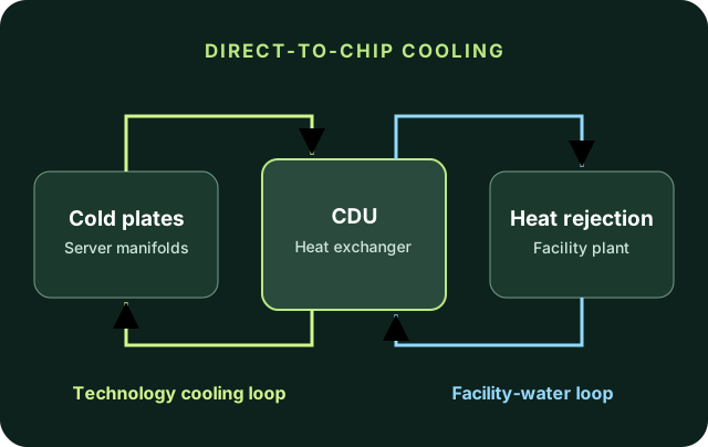
| Liquid-to-liquid | The CDU transfers heat to the facility water loop through a heat exchanger. | Check available facility flow, water temperature, pressure and chemistry. Check the CDU rating at those conditions and the target equipment coolant temperature. The room must still handle residual rack heat and any CDU heat released locally. |
For a liquid-to-liquid unit, use the cold-end approach temperature, the difference between equipment coolant leaving the CDU and facility water entering it. In an illustrative case, 27 °C facility supply plus a 5 K approach gives 32 °C equipment coolant supply. A warmer facility supply or a larger approach can put the equipment loop above the server’s limit. Use the vendor’s curve at your flow and heat load, and check both the OEM coolant temperature range and site dew point. ASHRAE data center design guidance
Check pressure drop and the pump operating point
Get the OEM pressure-drop and minimum-flow data for each server. Use the selected coolant and temperature to estimate losses through the rack’s cold plates, hoses, quick disconnects and manifold. Add losses in common pipework and any filter or exchanger losses outside the boundary of the published CDU pump curve.
For parallel server branches, add the branch flows to get the rack flow. Evaluate pressure loss along the most restrictive required-flow path, including shared sections, and check that other branches can be balanced. Confirm that the pump curve meets the resulting flow and head and that the operating pressures stay within equipment limits.
Check the operating point again in the planned maintenance or failure state. For a design with one spare pump or CDU, check how much flow and heat rejection the remaining equipment can deliver with one unit unavailable. Confirm the alarm and monitoring plan and the site acceptance measurements. Open Compute Project CDU performance and testing methodology
Compare CDU planning classes
Use the classes to shortlist configurations, then ask for verified capacity at your liquid load, site temperatures, flow and pressure drop. A 30 kW calculated liquid load calls for a review of the vendor’s duty point and your design margin before selecting equipment.
PROJECT CHECKLIST
What to send for a CDU sizing review
Share your rack plan and what you know about the site. Use the worksheet to estimate the liquid and air loads and the intake checklist to record operating conditions.
- Server models, quantities, expected concurrent peak power and any planned expansion.
- Liquid heat capture data and remaining air load per server and rack.
- OEM coolant type, supply temperature range, minimum branch flow and pressure-drop curves.
- Facility water conditions and capacity, or entering room air temperature, airflow and available room cooling.
- Connection layout, rack space, maintenance and redundancy requirements, and the conditions to verify at commissioning.